

Every successful overhead line installation depends on controlling tension, friction, and alignment before a conductor ever reaches its final sag. An overhead wire pulley gives crews that control by supporting heavy cable spans, guiding conductors through towers, and reducing damaging drag during stringing. In transmission, distribution, and fiber-optic projects, small setup errors can lead to sheath abrasion, excessive winch load, or costly rework. This article explains how pulley design, load rating, groove geometry, bearing quality, and fleet angle management work together to improve cable suspension. It also highlights practical selection points contractors can use when matching stringing blocks, conductor support pulleys, winches, and tensioners to real field conditions.
How Overhead Wire Pulleys Improve Cable Suspension
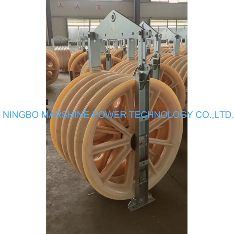
Stringing high-voltage lines or optical cables across challenging terrains is a complex engineering task. The backbone of this operation relies on the overhead wire pulley. Also known interchangeably throughout the industry as a conductor support pulley, stringing block, or pay-off pulley, this device precisely guides heavy conductors across transmission towers, drastically cutting down on friction and preventing costly abrasion damage to the cable sheathing.
Modern pulley configurations are designed to meet stringent industry standards, such as those set by IEEE 524 and IEC 61328, ensuring reliable performance during power grid construction. These tools feature precise groove profiles and bearing systems tailored to support various conductor types, providing engineers with reliable solutions for managing dynamic loads and complex suspension geometries rather than relying on generalized equipment.
Core Function and Performance Benefits
The primary job of any Conductor Support Pulley is to transform heavy dragging friction into rolling contact. When construction crews pull kilometers of dense conductor lines, integrating a high-quality pulley system can reduce the required pulling tension significantly. While often cited as a 30% to 40% reduction, these figures vary based on terrain, span length, and conductor type. This reduction in drag protects motorized winch equipment from overloading and prevents the conductor cable from stretching beyond its safe elastic limit.
Modern pulleys boast distinct characteristics like anti-jump mechanisms and ultra-smooth-rolling sealed bearings. This ensures that even during high-speed, high-tension pay-off operations, the cable stays securely seated within the machined groove, effectively mitigating the risk of sudden snaps, derailments, or mid-air line drops.
Key Load and Alignment Factors
Effective cable suspension requires precise, calculated load management. Depending on the span length and conductor weight, an overhead wire pulley might need to safely support loads ranging from 10 kN for standard local distribution lines up to 100 kN for ultra-high-voltage transmission towers. Engineers must also account for the sheave-to-cable diameter (D/d) ratio—typically 20:1 or 40:1 depending on the conductor type—which is a critical constraint that prevents cable kinking and bending damage.
Proper physical alignment is equally critical to the success of the pull. If the incoming fleet angle exceeds typical thresholds—often guided by standards like IEEE 524 to remain under 15 degrees, though this varies with specific sheave designs and rigging setups—the resulting lateral forces can cause premature, uneven wear on the pulley flanges and damage the outer protective layer of the conductor. Field crews can measure this fleet angle using digital inclinometers or laser alignment tools before initiating the pull. If the angle is too steep, technicians can correct the alignment by adjusting the tensioner settings or repositioning the temporary anchor slings. By maintaining strict alignment protocols and selecting pulleys with the optimal groove radius, construction teams minimize unwanted cable sag and ensure tension remains evenly distributed across the entire stringing block array.
Essential Specifications and Material Options
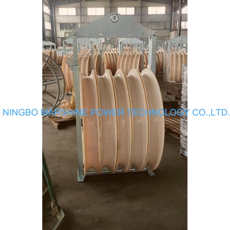
Moving beyond the basic mechanics of cable suspension, the physical characteristics of the pulley dictate how well it performs in field conditions. The modern electrical power equipment sector requires versatile solutions, leading developers to produce a wide array of purpose-built tools across multiple distinct series.
Whether a project involves pulling an optical fiber cable or a steel-cored aluminum strand, selecting the correct material configuration for the pay-off pulley is a critical step for a successful, long-lasting grid deployment.
Nylon Wheel vs Aluminum Wheel
The primary decision in material selection typically involves choosing between nylon and aluminum wheels, depending on the specific type of cable being deployed. MC nylon wheels are exceptionally lightweight and boast a remarkably low friction coefficient. This trait makes them ideal for protecting softer exteriors, such as fiber optic lines or soft-jacketed underground cables, without adding unnecessary bulk to the aerial rigging. However, field engineers must account for MC nylon's susceptibility to UV degradation over prolonged sun exposure and potential moisture absorption in highly humid environments.
Conversely, aluminum alloy wheels offer structural durability and excellent thermal heat dissipation. When pulling heavy-duty conductors over long, continuous spans, aluminum wheels prevent localized heat buildup that could otherwise degrade the cable jacket or melt the pulley bearings. While high-strength aluminum blocks easily handle continuous working loads exceeding 50 kN, crews must remain vigilant regarding potential galvanic corrosion when in contact with dissimilar metals, as well as thermal expansion during extreme temperature fluctuations.
While nylon and aluminum dominate the market as the standard binary choices, a third option exists for specialized low-abrasion stringing requirements: neoprene-lined pulleys. By combining a robust metal core with a soft, protective synthetic rubber lining, these hybrid pulleys provide enhanced grip and superior protection for highly sensitive cable jackets.
Specification Table for Professional Selection
To streamline the selection process, grid engineers and procurement teams frequently rely on standardized performance specifications. The following table breaks down generalized industry norms for the most common material types to help guide professional purchasing decisions.
| Pulley Material | Typical Wheel Diameter (mm) | Max Rated Load (kN) | Average Weight (kg) | Best Suited For |
|---|---|---|---|---|
| MC Nylon | 300 - 508 | 20 - 40 | 12 - 18 | Optical fiber, soft cables, standard aerial lines |
| Aluminum Alloy | 508 - 820 | 50 - 100 | 25 - 45 | Steel-cored aluminum, heavy transmission grids |
| Neoprene Lined | 400 - 660 | 30 - 60 | 20 - 30 | Specialized low-abrasion stringing requirements |
These figures highlight the fundamental engineering trade-offs between component weight, maximum load capacity, and specific application suitability. By analyzing these metrics, construction teams can accurately match the exact performance characteristic of the tool to the rigorous demands of the power grid.
How to Choose, Source, and Deploy Overhead Wire Pulleys
Deploying these construction tools effectively requires meticulous planning across the entire procurement and installation lifecycle. When choosing and sourcing overhead wire pulleys, procurement teams should establish actionable criteria rather than relying solely on brand reputation.
Further reading:
Key Takeaways
- Use overhead wire pulleys to convert dragging friction into rolling contact and reduce conductor abrasion during long-distance stringing.
- Match pulley load capacity to the project, with common requirements ranging from about 10 kN for distribution lines to 100 kN for heavy transmission work.
- Check the sheave-to-cable diameter ratio before pulling, because ratios such as 20:1 or 40:1 help limit bending stress and cable deformation.
- Measure and control fleet angle before the pull, keeping it within the pulley manufacturer’s guidance or standards such as IEEE 524 to prevent side loading.
- Choose pulleys with sealed bearings, anti-jump protection, and correct groove geometry to improve safety during high-tension pay-off operations.
Frequently Asked Questions
What does an overhead wire pulley do during cable stringing?
It guides conductors or optical cables over towers and supports while converting dragging friction into rolling contact, reducing abrasion, tension spikes, and pulling load on winches.
How much can a stringing pulley reduce pulling tension?
A suitable pulley system can often reduce pulling tension by about 30% to 40%, though results depend on terrain, span length, conductor weight, and alignment.
Why is the sheave-to-cable diameter ratio important?
The D/d ratio helps prevent kinking and bending damage. Common targets include 20:1 or 40:1, depending on conductor type, cable construction, and project requirements.
What load capacity should an overhead wire pulley have?
Select capacity based on conductor weight, span length, and safety factors. Typical applications may range from 10 kN for distribution work to 100 kN for heavy transmission projects.
How does fleet angle affect cable suspension?
Excessive fleet angle creates side loading, flange wear, and conductor sheath damage. Many projects use limits near 15 degrees, but the correct limit depends on pulley design and rigging.