

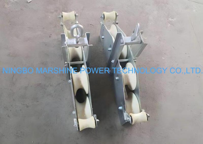
A fiber cable can be permanently weakened long before it visibly fails, which is why pulley selection is more than a hardware choice. The right optical fiber cable pulley controls bending radius, pulling tension, jacket contact, and cable stability throughout the stringing route. This guide explains how to match pulley specifications to ADSS and OPGW cable types, calculate sheave size using D/d ratios, verify SWL or WLL ratings, and account for field conditions such as wind, long spans, grounding, and terrain. By focusing on measurable requirements instead of generic block sizes, contractors can protect fiber performance, improve installation safety, and reduce costly rework.
Define the Optical Fiber Cable Pulley Requirements
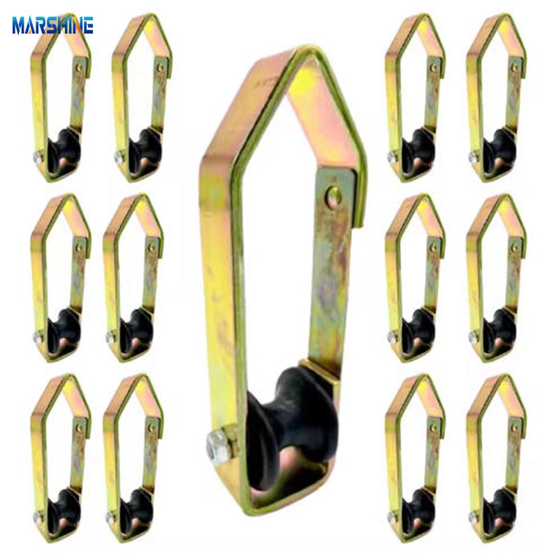
Getting a fiber optic network installed efficiently requires precision, and the optical fiber cable pulley is central to that operation. Standard blocks—typically featuring unlined steel V-grooves and unsealed bearings—cannot safely handle delicate fiber cables. It is critical to distinguish between ADSS (all-dielectric, distribution-class) and OPGW (metallic, transmission-class) cables, as they require significantly different installation protocols. OPGW installation typically follows traditional conductor stringing practices and requires strict grounding, whereas ADSS requires all-dielectric, non-conductive blocks. Selecting the right pulley means focusing on specific engineering features that mitigate crushing forces and excessive bending during installation.
Key Pulley Parameters to Confirm First
The most critical parameter to establish is the wheel diameter, which must comply with the cable manufacturer's minimum bend radius specifications and the required D/d ratio (the ratio of the sheave diameter to the cable diameter). Industry standards commonly specify minimum ratios, such as 40:1 for ADSS cables, to prevent irreversible micro-bending attenuation and structural damage. Rather than relying on broad fixed ranges, calculate the required wheel diameter directly from the cable's engineering data. Alongside diameter, always verify the Safe Working Load (SWL) or Working Load Limit (WLL), depending on regional standards. Calculate the necessary load rating based on the maximum pulling tension, span-loading engineering data, and the specific weight of the cable being installed, referencing standards such as IEEE 524 for overhead transmission line stringing.
Project Conditions That Affect Pulley Selection
The installation environment dictates the required gear. When working in tight urban pole routes versus long-span mountainous transmission lines, your fiber optic stringing block needs specific features to match the terrain. For high-wind areas or long spans where tension fluctuates unpredictably, pulleys equipped with anti-jumping side plates are strongly recommended. These plates prevent the cable from derailing during severe wind gusts or sudden tension changes. For all overhead stringing hardware, the pulley's groove must be smoothly machined to minimize jacket abrasion as the cable passes through. Furthermore, when installing OPGW, strict grounding protocols are essential; failing to properly ground metallic optical ground wires during stringing operations creates severe electrical hazards. Refer to IEEE 524 guidelines for proper grounding practices during installation.
Compare Optical Fiber Cable Pulley Specifications
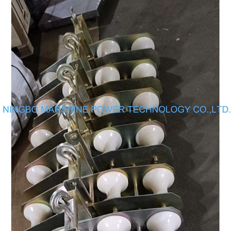
Once baseline requirements are established, evaluate materials and build quality. An optical fiber cable pulley is a specialized tool; the wheel material dramatically changes its performance, overall weight, and interaction with the cable jacket. Finding the right balance ensures crews can safely handle the equipment while protecting the fiber.
Nylon, Aluminum, and Steel Pulley Wheels
Industry standards typically utilize nylon and aluminum for fiber applications. Nylon wheels, specifically MC nylon, are lightweight and gentle on ADSS cable jackets, offering a very low coefficient of friction. However, MC nylon is susceptible to cold-temperature brittleness and UV degradation, which must be factored into outdoor utility work in extreme climates. Aluminum wheels, often rubber-lined, provide the higher durability required for heavier, metallic OPGW cables. Steel is generally reserved for heavy wire ropes and pulling lines; it should not directly contact fiber cables to avoid severe abrasion.
| Material | Best For | Approximate Weight (600mm)* | Friction Profile | Key Feature |
|---|---|---|---|---|
| MC Nylon | ADSS Cables | 8 - 12 kg | Very Low | Minimal abrasion risk |
| Aluminum (Rubber-lined) | OPGW Cables | 15 - 25 kg | Low to Moderate | High crush resistance |
| Steel | Wire Ropes / Pulling Lines | 30+ kg | High | Maximum load capacity |
*Note: Weights are approximate examples; actual weight varies widely based on frame design.
Product Data and Supplier Checks
Beyond physical materials, evaluate the manufacturer's product data, engineering standards, and quality assurance processes. A high-quality fiber optic cable pulley features sealed deep-groove ball bearings to keep dust and moisture out, ensuring smooth rotation under heavy loads. Check the bearing sealing ratings to confirm they are suitable for the specific job-site environment. Always look for manufacturers that hold current quality system certifications, such as ISO 9001:2015. Sourcing from established suppliers with verified engineering datasheets ensures the equipment is backed by stringent quality standards. This helps prevent out-of-box failures and ensures the pulleys will not seize up mid-pull, which could otherwise cause sudden tension increases and cable damage.
Choose the Right Optical Fiber Cable Pulley
Selecting the proper stringing equipment requires integrating technical specifications, project environment data, and supplier reliability. The objective is to deploy a setup that prevents costly cable damage while keeping the installation crew moving efficiently and safely across the grid.
Step-by-Step Selection Process
Follow a systematic checklist to ensure proper pulley selection:
- Verify Groove Geometry: As a common manufacturer guideline, specify a rounded U-groove with a groove diameter roughly 1.1 to 1.25 times the cable's outside diameter (always verify against specific cable designs and national codes). A groove radius larger than this range can be unstable and fail to center the cable, while a smaller radius creates pinch-point risks.
- Check Compatibility: Ensure the pulley design is fully compatible with the stringing grips, pulling socks, and swivels that will pass through it.
- Calculate Tension: Determine your maximum stringing tension using proper engineering inputs—such as sag-tension charts, ruling span length, and friction coefficients—and select a wheel material that supports this load without adding unnecessary weight.
- Confirm Alignment and Geometry: Verify sheave alignment and the block mounting angle. Even a correctly sized pulley can cause severe cable damage if the setup geometry is incorrect and forces the cable to ride against the sheave flanges.
Final Decision Factors
Logistical and maintenance factors are just as critical as technical specifications. When it comes to procurement and logistics, check Minimum Order Quantities (MOQs) and lead times with an established manufacturer, as custom rubber-lined aluminum wheels often require extended manufacturing windows. Securing these details early prevents project delays.
Equally important is establishing a protocol for long-term maintenance.
Further reading:
Key Takeaways
- Confirm the cable type first, because ADSS typically needs all-dielectric non-conductive blocks while OPGW requires grounding and conductor-style stringing precautions.
- Calculate sheave diameter from the cable manufacturer’s minimum bend radius and D/d ratio, with 40:1 commonly used as a minimum reference for ADSS.
- Select the pulley SWL or WLL based on maximum pulling tension, cable weight, span-loading data, and relevant standards such as IEEE 524.
- Use anti-jumping side plates on long spans, windy routes, or uneven terrain to reduce the risk of cable derailment during tension changes.
- Choose wheel material by application: MC nylon is light and jacket-friendly for ADSS, while rubber-lined aluminum is often better for heavier OPGW installations.
Frequently Asked Questions
What makes an optical fiber cable pulley different from a standard stringing block?
Fiber cable pulleys use cable-friendly groove profiles, suitable wheel materials, and smoother bearings to reduce crushing, abrasion, and micro-bending. Standard steel V-groove blocks can damage delicate ADSS or OPGW cables.
How do I choose the correct sheave diameter for fiber cable stringing?
Use the cable manufacturer’s minimum bend radius and D/d ratio requirements. For many ADSS applications, a 40:1 ratio is common, but the final sheave diameter should be calculated from the actual cable diameter and engineering data.
Should ADSS and OPGW cables use the same pulley?
Not usually. ADSS requires non-conductive, jacket-friendly blocks, while OPGW is metallic and often needs more durable sheaves plus strict grounding procedures. Selection should follow the cable type and project stringing standard.
What does SWL or WLL mean when selecting a pulley?
SWL or WLL is the rated load the pulley can safely handle. It should be chosen based on maximum pulling tension, span conditions, cable weight, and applicable stringing standards such as IEEE 524.
When are anti-jumping side plates necessary?
Anti-jumping side plates are recommended for long spans, high-wind areas, mountainous routes, or any installation where tension may fluctuate. They help prevent the cable from leaving the groove during stringing.