

Twin-bundle transmission work leaves little margin for error: two energized-route conductors, heavy mechanical loads, and strict spacing requirements all have to be controlled at once. A properly selected conductor lifter gives line crews a defined load path from the hoist to a rigid yoke and into two secured clamps, helping prevent slippage, abrasion, and sudden imbalance. This article explains how twin-bundle lifters improve safety on 220kV to 500kV lines, what structural features matter most, and how Working Load Limit, conductor type, bundle geometry, and standards such as ASME B30.20 or IEC 61284 should guide selection.
How Twin-Bundle Conductor Lifters Improve Safety
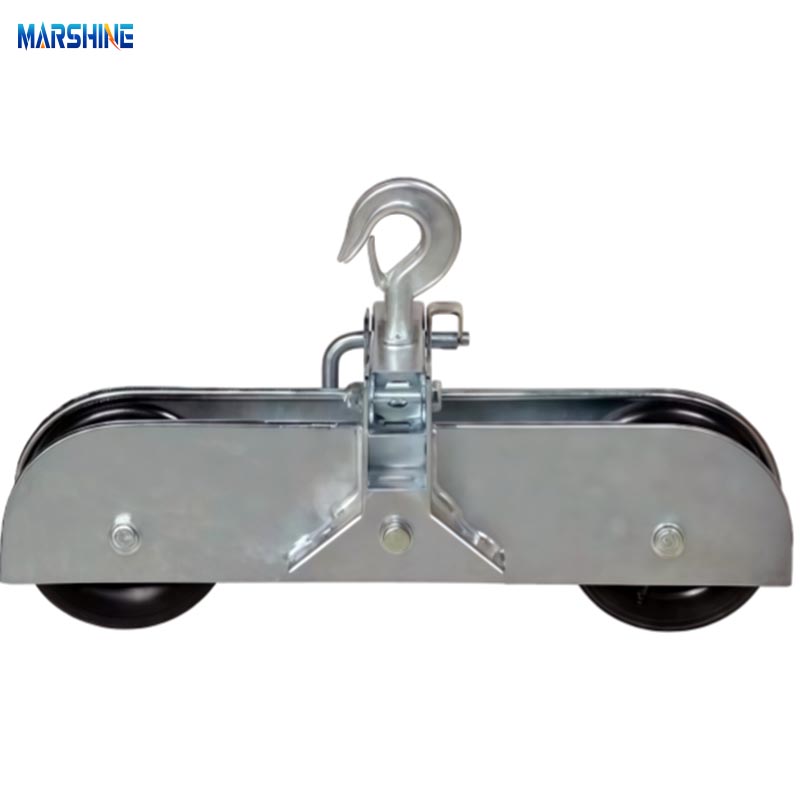
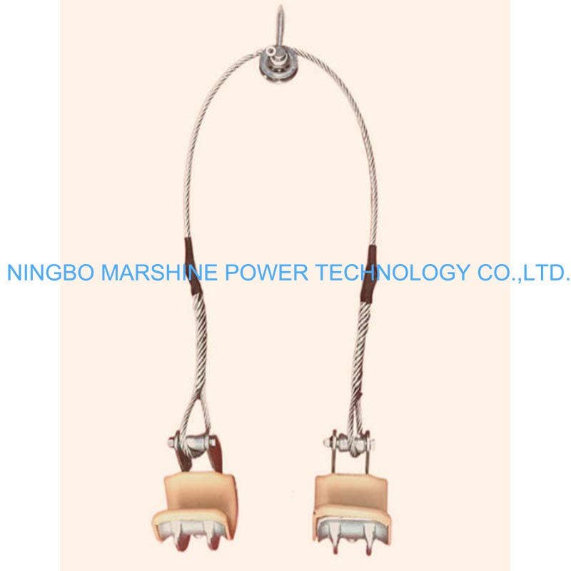
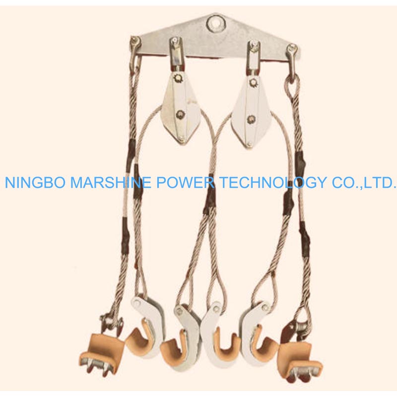
Upgrading transmission lines to twin-bundle configurations introduces serious physical risks and rigging challenges. While certified operators must first verify electrical safety prerequisites—such as live-line restrictions, minimum approach distances, and bonding or grounding requirements—the mechanical challenge requires specialized lifting hardware. These lifters safely handle twin-bundle dynamics through a clear mechanical load path: the combined weight transfers from a central lifting point through a rigid yoke, distributing the force evenly to dual independent clamps secured around the sub-conductors. This mechanism maintains exact spacing and allows line crews to avoid dangerous improvised rigging that frequently leads to cable slippage or worker injury.
Twin-bundle lifting applications
Twin-bundle setups are the standard for 220kV to 500kV high-voltage transmission lines, specifically designed to reduce corona discharge and line noise. Lifting these bundles requires tools engineered to support the combined weight—often exceeding 30 kN—while maintaining the exact spacing between the cables. Utility contractors deploy these lifters during insulator replacement, stringing operations, and sag adjustments. Depending on the specific product class, heavy-duty twin-bundle lifters are rated to Working Load Limits (WLL) sufficient to safely support long spans of heavy conductors without risking sudden drops. However, lifter requirements vary significantly depending on the conductor material (such as ACSR, ACSS, or ACCC), specific bundle geometry, and regional electrical codes, meaning a single specification does not fit all scenarios.
Key structural and safety features
The structural integrity of these lifters relies on high-strength forged alloy steel and precision-machined yokes. Key product features include anti-slip, rubber-lined clamping jaws that protect the conductor's delicate outer strands from crushing forces. Safety is further bolstered by self-locking pins and design factors dictated by jurisdictional standards and specific application requirements. Equipment manufacturers integrate these fail-safes so that even under sudden wind gusts or dynamic load shifts, the twin conductors remain securely cradled. Additionally, lifting hardware must be periodically inspected and recertified per ASME B30.20 (Below-the-Hook Lifting Devices) or relevant standards such as IEC 61284 for overhead line fittings. Operators must also account for critical operational caveats, such as controlling rotation and swing during non-vertical lifts, because any lifter tilt risks uneven loading and severely compromises twin-bundle stability.
Specifications and Selection Factors
Selecting the appropriate conductor lifting tool requires strict adherence to a project's specific engineering constraints. It requires matching the tool's structural specifications and safety limits to the exact dimensions and weight of the bundled conductors being installed or maintained.
Single-conductor vs twin-bundle lifters
While single-conductor lifters feature a relatively straightforward vertical load path, twin-bundle variants must account for a shifted center of gravity and complex rigging geometry between two independent lines. The integrated yoke must balance the load perfectly to prevent uneven tension, clashing, and surface abrasions during the lift. Disclaimer: The table below provides generalized examples; actual specifications must be verified against recognized standards, named product lines, and local code requirements.
| Specification | Single-Conductor Lifter (Example) | Twin-Bundle Lifter (Example) |
|---|---|---|
| Working Load Limit (WLL) | 15 kN – 25 kN | 30 kN – 60 kN |
| Sub-Conductor Spacing | N/A | 400 mm – 500 mm |
| Tool Weight | 8 kg – 15 kg | 20 kg – 35 kg |
| Primary Use Case | Distribution, sub-110kV | Transmission, 220kV+ |
Site variables to verify before purchase
Before procurement, project managers must verify several site-specific variables. Conductor diameter is the first checkpoint; many twin-bundle clamps are engineered to accommodate variable ranges, but crews must consult engineering specifications to ensure a proper fit for their specific cable. Engineers must also calculate the temperature-adjusted sag tension and dynamic wind-load coefficients the lines will experience while suspended, as extreme temperature variations can alter cable tension and dictate whether a standard or heavy-duty clamp is required. If crews are working in environments prone to high winds, selecting a lifter with an extended clamping surface distributes the grip pressure evenly and prevents the cables from bowing or slipping out of alignment.
Buying and Use Guidance for Utilities and Contractors
Even the most advanced conductor lifting device must be paired with strict operational protocols and sourced from a reliable supplier. Utilities and contractors must balance field practicality with long-term equipment reliability to keep grid construction projects on schedule and within budget while meeting strict safety targets.
Practical lifting steps
In the field, practical lifting follows a strict step-by-step process. First, crews perform a rigorous pre-lift inspection to check for micro-fractures in the lifter's yoke or wear on the locking pins. Second, trained operators position the lifter over the twin bundle, ensuring the cables are perfectly seated in the padded grooves. Third, operators tighten the clamps with precision; torqueing the securing bolts to the manufacturer's recommended setting ensures a firm grip without deforming the aluminum strands. Fourth, the lift is executed in slow, synchronized increments using a compatible crane or hoist. During this phase, it is critical to keep the twin bundle perfectly level to avoid uneven weight distribution on the insulators. Finally, a post-lift conductor strand inspection ensures no surface damage occurred during the operation.
Quality certification and supplier checks
When sourcing these critical tools, thorough supplier vetting is non-negotiable. Procurement teams should prioritize equipment that complies with recognized third-party testing standards, such as IEC or ASTM. Rather than relying solely on generic quality management certifications, buyers must evaluate conductor-lifter-specific procurement criteria. Essential requirements include adjustable yoke ranges to accommodate varying bundle geometries, jaw compatibility with specific conductor diameters, and documented proof-test certificates for each unit. Selecting a supplier that provides transparent technical documentation and readily available replacement parts ensures that line crews are equipped with verifiable, code-compliant tools for high-tension environments.
Further reading:
Key Takeaways
- Use a twin-bundle conductor lifter with a rigid yoke and dual clamps to keep both sub-conductors evenly supported during lifting.
- Verify the Working Load Limit before use because twin-bundle lifting loads can exceed 30 kN on heavy transmission spans.
- Match the lifter to conductor material, bundle spacing, clamp size, and local electrical codes rather than relying on one universal specification.
- Choose lifters with anti-slip rubber-lined jaws and self-locking pins to reduce conductor damage and prevent accidental release.
- Inspect and recertify lifting hardware according to applicable standards such as ASME B30.20 or IEC 61284 before critical line work.
- Control swing, rotation, and non-vertical lift angles because lifter tilt can create uneven loading and compromise bundle stability.
Frequently Asked Questions
What is a twin-bundle conductor lifter used for?
It is used to lift and support two sub-conductors at the same time during transmission line work, including insulator replacement, stringing operations, sag adjustment, and maintenance on high-voltage twin-bundle lines.
Why can’t crews use a single-conductor lifter for twin bundles?
Twin bundles need balanced support across two conductors. A single-conductor lifter cannot maintain spacing, load balance, or stable geometry, increasing the risk of slippage, abrasion, uneven tension, and unsafe rigging.
What voltage ranges commonly use twin-bundle conductors?
Twin-bundle conductors are commonly used on 220kV to 500kV transmission lines because they help reduce corona discharge, electrical losses, and line noise on high-voltage systems.
What features improve conductor lifter safety?
Important safety features include a rigid yoke, dual independent clamps, anti-slip rubber-lined jaws, forged alloy steel construction, self-locking pins, and a Working Load Limit matched to the conductor weight and span.
How should crews choose the correct conductor lifter?
Crews should verify the conductor material, bundle spacing, total load, clamp size, Working Load Limit, applicable standards, and site conditions before selecting lifting hardware from a qualified supplier such as cable-winch.com.