

OPGW installation leaves little room for guesswork: a clamp that holds too aggressively can damage optical fibers, while one that slips can create unsafe line tension. Because Optical Ground Wire functions as both a shield wire and a communication pathway, tool selection must account for cable diameter, bend radius, Rated Tensile Strength, route geometry, and verified Safe Working Load. This guide explains how to assess clamping requirements, compare essential OPGW stringing tools such as come-along clamps and cable rollers, and avoid common mistakes that lead to fiber attenuation or outer-layer deformation. The goal is practical and safety-focused: help crews choose equipment that grips securely without compromising cable performance.
Define Safe OPGW Clamping Requirements
Stringing Optical Ground Wire (OPGW) is a fundamentally different task than installing standard ACSR conductors. Because OPGW serves a dual purpose—acting as both a grounding wire and a high-speed communication link—the delicate optical fibers hidden inside require exceptional care. If a crew applies uneven pressure or uses the wrong hardware, they risk crushing the internal stainless steel tubes or causing micro-bending in the fibers, which leads to permanent signal attenuation. Defining safe clamping requirements is the crucial first step to protecting the cable's integrity during installation, ensuring that OPGW stringing tools perform safely under high radial compression and longitudinal tension.
Cable and route parameters affecting clamp safety
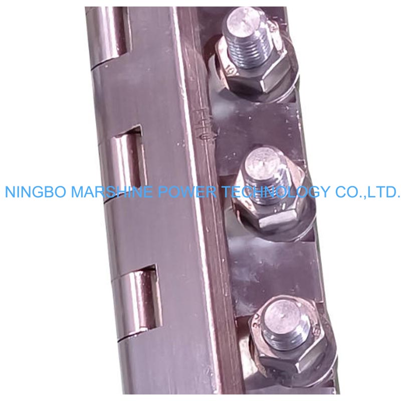
The physical route of the transmission line heavily dictates the specific design attributes necessary for safe clamping. Span lengths, elevation changes, and line deviation angles all multiply the stress placed on the cable. For example, on long river crossings exceeding 600 meters or at tension towers where deviation angles reach up to 30 degrees, the lateral and pulling forces increase dramatically. To counter this, high-quality clamps feature elongated aluminum alloy jaws specifically designed to distribute radial pressure over a much larger surface area. This extended gripping profile is a critical functional specification that prevents localized crushing, keeping the pressure well below the cable's damage threshold while maintaining a secure, slip-free hold.
Required grip, bend radius, and tension limits
Staying strictly within mechanical limits is non-negotiable for fiber safety. Installation crews must meticulously monitor the minimum bend radius, which is typically mandated at 40 to 50 times the cable's outer diameter (often translating to a strict 400mm to 600mm radius limitation). Tension is another major factor; standard practice requires keeping pulling tension below 15% to 20% of the cable's Rated Tensile Strength (RTS). Absolute kN limits, such as a 15 kN to 25 kN range, cannot be generalized; they must be derived directly from the specific cable's RTS.
It is important to note that installation is performed on bare cable under controlled conditions. Therefore, environmental extremes like heavy ice loading are operational design factors for the final line, rather than direct inputs that require a proportional reduction in a stringing clamp's Safe Working Load (SWL) during installation. However, extreme temperature drops during the stringing process can increase cable brittleness, necessitating careful tension management to prevent fiber strain.
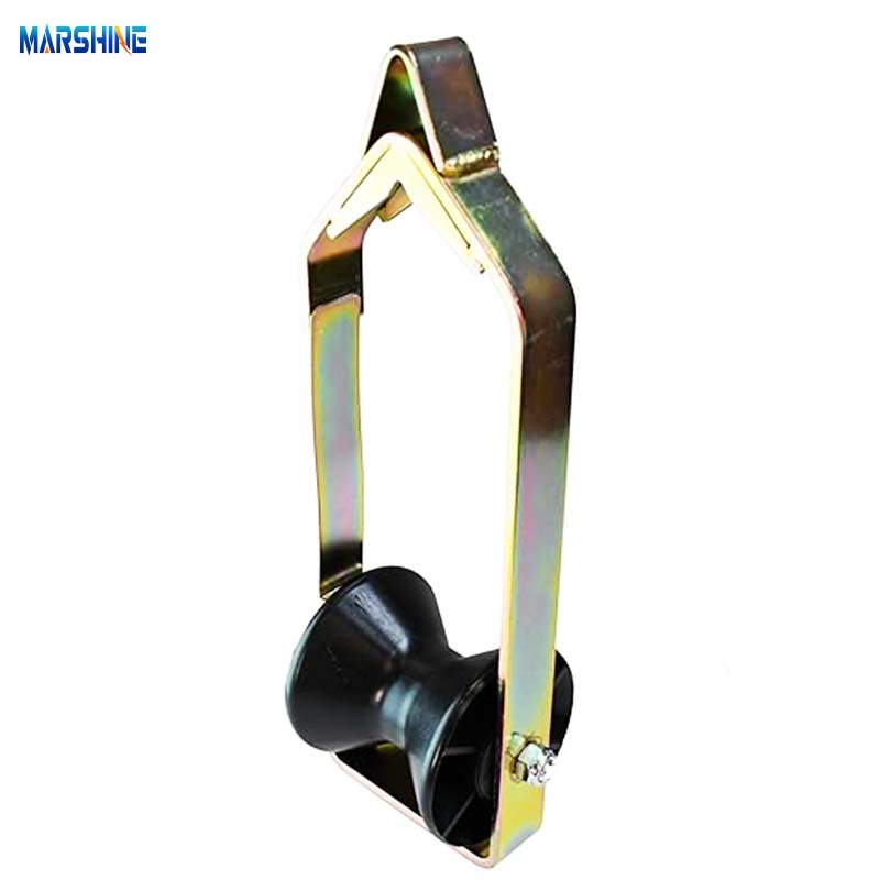
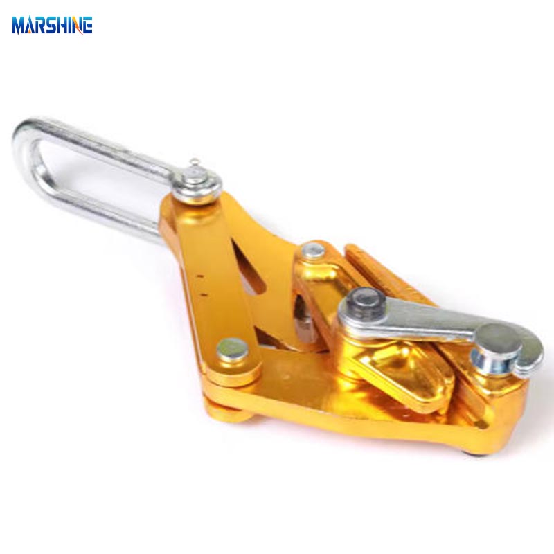
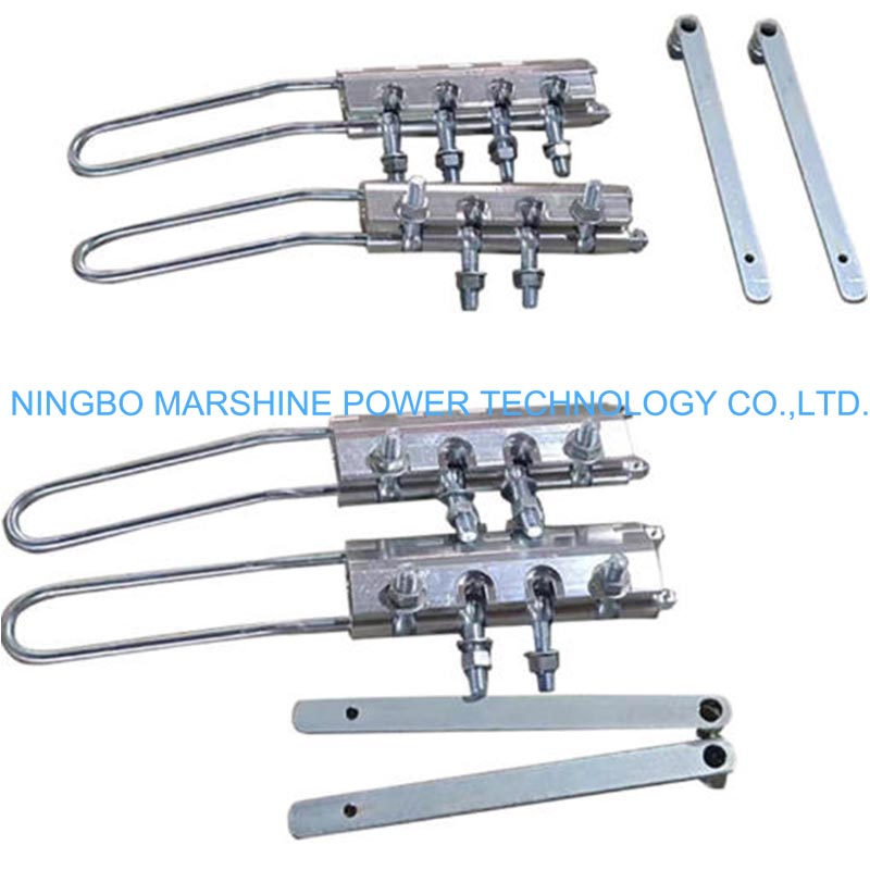
Using specialized equipment like cable rollers makes it much easier to maintain the minimum bend radius. These tools act as essential friction-management pulleys. Meanwhile, gripping devices like come-along clamps incorporate contoured grip grooves and precisely calibrated spring mechanisms that apply a calculated clamping pressure to manage the tension without deforming the aluminum-clad steel outer layers.
Compare OPGW Stringing Tools and Suppliers
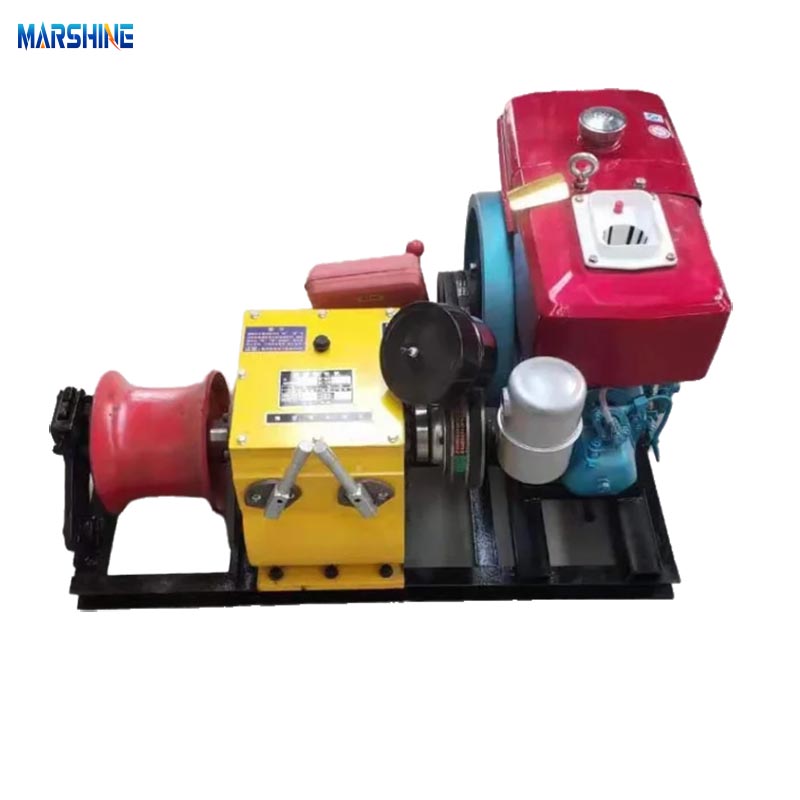
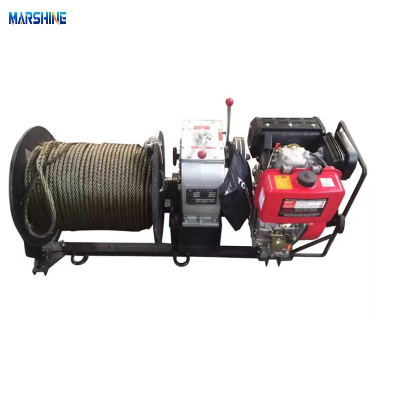
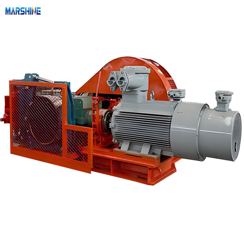
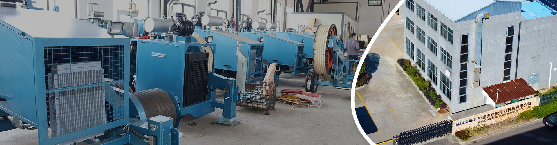
Once the project's technical thresholds are mapped out, it is time to evaluate the actual hardware and the manufacturers behind it. The market offers a vast array of equipment, but standard conductor tools are rarely suitable for delicate fiber optics. Partnering with an experienced, certified manufacturer ensures access to equipment specifically engineered for these challenges. When evaluating suppliers, look for comprehensive catalogs that include specialized cable pulling winches, universal stringing blocks, and come-along clamps, ensuring crews can find exactly what they need for safe aerial cable operations.
Come-along clamps, stringing blocks, and tensioners
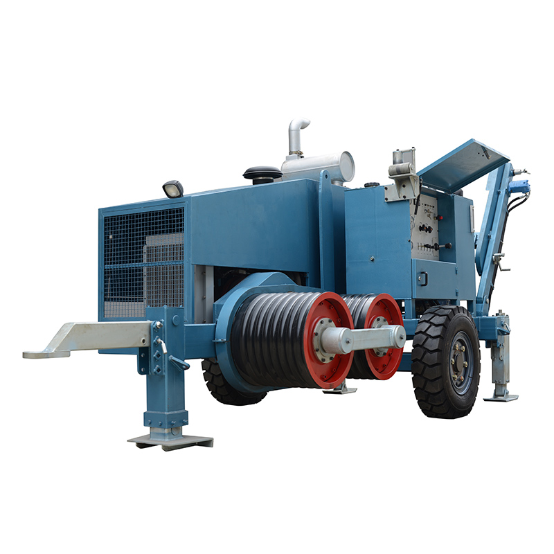
A typical stringing operation relies heavily on the coordinated interaction of come-along clamps, stringing blocks, and tensioners. During a standard pulling sequence, the tensioner pays out the OPGW under controlled braking to maintain clearance, while stringing blocks suspended from towers guide the cable and enforce the minimum bend radius. Once the cable reaches the target span, come-along clamps temporarily grip the OPGW to pull it to its final sagging tension before permanent dead-ends are installed.
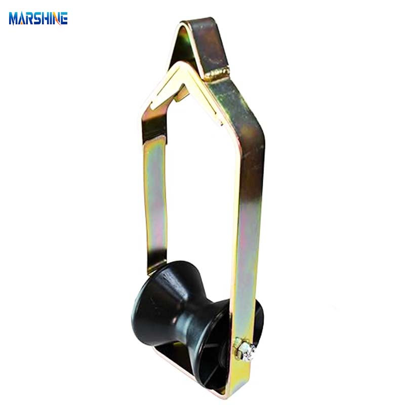
Each piece of equipment requires distinct functional specifications tailored specifically for OPGW. Come-along clamps must utilize smooth, non-serrated jaws to avoid scoring the cable's surface. Stringing blocks (pulleys) demand large-diameter wheels lined with neoprene or nylon to cushion the cable and strictly enforce bend radius limits. Tensioners rely on large bullwheels with customized nylon segments to prevent wire twisting.
| Tool Type | Key Design Attribute | Typical Specification Limit |
|---|---|---|
| Come-Along Clamp | Extended, smooth aluminum alloy jaws | Safe Working Load: 20 kN – 50 kN |
| Stringing Block | Neoprene-lined nylon/aluminum wheels | Minimum wheel diameter: 600mm – 800mm |
| Bullwheel Tensioner | Multi-groove wheels with nylon segments | Max tension control: < 20% of RTS |
Manufacturer capability and sourcing checks
Evaluating a manufacturer's capability and production standards is just as important as inspecting the tool itself. Rather than relying solely on generic B2B markers, buyers should demand OPGW-specific vetting criteria. Reliable suppliers provide material certifications, dimensional inspection reports, and verified compliance with IEEE 524 or equivalent stringing standards to ensure their clamps will not damage internal tubes. These criteria help enforce rigorous procurement standards, including mandatory factory acceptance tests (FAT) and witnessed third-party load testing. When evaluating a reputable supplier, prioritize specific, verifiable sourcing criteria like material traceability for aluminum alloy jaws and verified jaw geometry compatibility. This provides essential assurance when ordering specialized equipment for large-scale grid construction.
Select and Verify the Right OPGW Stringing Tool
Selecting the final equipment requires a highly methodical approach to ensure every piece of hardware perfectly aligns with the project's specific OPGW cable. A mismatch between the cable's outer diameter, its construction type, and the tool's gripping mechanism is a leading cause of costly installation failures and fiber damage. Tool selection differs significantly between central-tube and stranded OPGW designs. Central-tube designs are highly sensitive to radial crush forces, requiring clamps with longer, precisely contoured jaws to distribute pressure over a wider area.
Further reading:
Key Takeaways
- Verify bend radius, pulling tension, and clamp Safe Working Load against the OPGW manufacturer’s datasheet before selecting any stringing tool.
- Maintain a minimum bend radius commonly around 40 to 50 times the cable diameter to reduce the risk of fiber micro-bending.
- Limit installation pulling tension to the project-approved value, often estimated at 15% to 20% of the cable’s Rated Tensile Strength.
- Choose OPGW clamps with elongated aluminum alloy jaws and contoured grooves to spread radial pressure and prevent localized crushing.
- Use cable rollers to manage friction and cable curvature, especially on long spans, elevation changes, and angled tower sections.
- Evaluate route conditions such as spans over 600 meters and deviation angles near 30 degrees before confirming tool capacity and clamp design.
Frequently Asked Questions
Why do OPGW cables need specialized stringing tools?
OPGW contains optical fibers inside a grounding wire structure, so standard conductor tools can create crushing, uneven pressure, or micro-bending that permanently increases signal attenuation.
What bend radius should crews maintain during OPGW stringing?
A common planning range is 40 to 50 times the cable outer diameter, but the exact minimum bend radius must always be confirmed from the OPGW manufacturer’s datasheet.
How much pulling tension is typically allowed for OPGW installation?
Crews often limit pulling tension to about 15% to 20% of the cable’s Rated Tensile Strength, but the final kN limit must be calculated from the specific cable design.
What clamp features help prevent OPGW damage?
Look for elongated aluminum alloy jaws, smooth contoured grooves, calibrated clamping pressure, and a Safe Working Load that matches the route tension requirements.
When are higher-capacity OPGW stringing tools needed?
Higher-capacity tools may be needed on long spans, steep elevation changes, river crossings over 600 meters, or tension towers with deviation angles approaching 30 degrees.